Today at work, I came to the conclusion that Broadband matching is a fine art. It takes years of experience to understand and get it right. Even the most experienced RF Engineers still have issues developing a matching network for amplifiers and power transistors.
I'm going to give a brief overview of Broadband matching and how it applies to the RF engineer.
The Basics
A matching network is simply any network that can transform impedances from it's input to output. Generally, they consist of either LC networks or microstrip equivalents. They come in the form of filter type matches. I have mostly used strings of networks with the high pass and low pass structure.
There are many ways to match networks and many structures you can use. At low frequencies (under 1 GHz) and at narrow bandwidths (under 100 MHz) it's generally easier to match using the Smith Chart. At higher frequencies and higher bandwidths, I recommend a more trial and error approach. This is what broadband matching entails (higher bandwidths). There is no single method to broadband matching, so I'll show you my method and then only with amplifier/transistors.
My Method
So let's say we have an RF amplifier that is denoted like so:

Every amp has an inherent input impedance and output impedance. This is modeled by something like so:

Now generally, input impedances are meant to be extremely high (Megaohms in Op-Amps) but in RF amps they can be very small (sometimes 2 - 3 ohms). The output can be almost anything, but generally smaller.
Now something to notice, is the inherent resistances. Most of the time they are not strictly resistive and will be reactive as well. I noticed today that the amp I was using was in fact inductive at high frequencies. So I had to match accordingly.

Since Rin = Lin, I began my matching with a series capacitor like so:
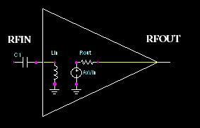
So you see, I used the internal inductor as my first component, then use the series capacitor to complete this first part of the match (High Pass Filter).
To shorten this post up a little bit, I will say that you will then put a shunt capacitor as the next component, then a series inductor, etc, etc. Repeat those until you have a match. Do the same for the output.
Now the big question you'll be asking is "what about the values?" Well this is where the art comes in. It's not a very simple topic to go through. This is completely dependent on what frequency return loss goals you have and how many networks you have. I generally use an optimizer in Agilent's ADS Simulation Software (EESof).
But I will give you a general overview of what "type" of values you'll need for certain frequency ranges:
HIGH FREQUENCY (500MHz-2GHz)
- Shunt C: Very low values (0.1pF - 2pF)
- Shunt L: Medium values (50nH - 100nH)
- Series C: Medium RF values (20pF - 50pF) [These are more dependent on other factors]
- Series L: Very low values (1.6nH - 15nH)
LOW FREQUENCY ( < 500MHz)
- Shunt C: Medium values (100pF - 1uF)
- Shunt L: High Values (1uH - 100uH) [This is a guesstimate]
- Series C: High RF values (1000pF - 10uF)
- Series L: Medium values (100nH - 10uH)
I hope this post is somewhat useful. I know it's vague on details but I want to give you an idea on broadband matching. I can't really write a whitepaper on it for a post. If you have specific questions email/comment and ask. Later
--------------------
Justin Coulston
justin.coulston@gmail.com
No comments:
Post a Comment