Search This Blog

Showing posts with label electrical engineer. Show all posts

Thursday, April 29, 2010

RF: Broadband Matching

Introduction
Today at work, I came to the conclusion that Broadband matching is a fine art.  It takes years of experience to understand and get it right.  Even the most experienced RF Engineers still have issues developing a matching network for amplifiers and power transistors.

I'm going to give a brief overview of Broadband matching and how it applies to the RF engineer.

The Basics
A matching network is simply any network that can transform impedances from it's input to output.  Generally, they consist of either LC networks or microstrip equivalents.  They come in the form of filter type matches.  I have mostly used strings of networks with the high pass and low pass structure.

There are many ways to match networks and many structures you can use.  At low frequencies (under 1 GHz) and at narrow bandwidths (under 100 MHz) it's generally easier to match using the Smith Chart.  At higher frequencies and higher bandwidths, I recommend a more trial and error approach.  This is what broadband matching entails (higher bandwidths).  There is no single method to broadband matching, so I'll show you my method and then only with amplifier/transistors.

My Method
So let's say we have an RF amplifier that is denoted like so:


Every amp has an inherent input impedance and output impedance.  This is modeled by something like so:


Now generally, input impedances are meant to be extremely high (Megaohms in Op-Amps) but in RF amps they can be very small (sometimes 2 - 3 ohms).  The output can be almost anything, but generally smaller.

Now something to notice, is the inherent resistances.  Most of the time they are not strictly resistive and will be reactive as well.  I noticed today that the amp I was using was in fact inductive at high frequencies.  So I had to match accordingly.  


Since Rin = Lin, I began my matching with a series capacitor like so:
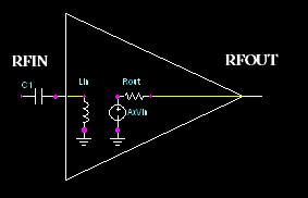

So you see, I used the internal inductor as my first component, then use the series capacitor to complete this first part of the match (High Pass Filter).

To shorten this post up a little bit, I will say that you will then put a shunt capacitor as the next component, then a series inductor, etc, etc.  Repeat those until you have a match.  Do the same for the output.

Now the big question you'll be asking is "what about the values?"  Well this is where the art comes in.  It's not a very simple topic to go through.  This is completely dependent on what frequency return loss goals you have and how many networks you have. I generally use an optimizer in Agilent's ADS Simulation Software (EESof).

But I will give you a general overview of what "type" of values you'll need for certain frequency ranges:

HIGH FREQUENCY (500MHz-2GHz)
  • Shunt C: Very low values (0.1pF - 2pF)
  • Shunt L: Medium values (50nH - 100nH)
  • Series C: Medium RF values (20pF - 50pF) [These are more dependent on other factors]
  • Series L: Very low values (1.6nH - 15nH)
LOW FREQUENCY ( < 500MHz)
  • Shunt C: Medium values (100pF - 1uF)
  • Shunt L: High Values (1uH - 100uH) [This is a guesstimate]
  • Series C: High RF values (1000pF - 10uF)
  • Series L: Medium values (100nH - 10uH)
I hope this post is somewhat useful.  I know it's vague on details but I want to give you an idea on broadband matching.  I can't really write a whitepaper on it for a post.  If you have specific questions email/comment and ask.  Later

--------------------
Justin Coulston
justin.coulston@gmail.com

Tuesday, April 6, 2010

Component Selection: Samples are the Key

Today I found out what was important in a manufacturing company: samples.

I have been trying to get samples for about a week from a company producing a candidate LNA for a project of mine.  But for some reason I just can't get a sample.  I've tried everything.  It's not like the part is $250.  These are $10 parts.  But when I tried to get samples from ATC and Coilcraft they gave them to me joyfully!  And I mean joyfully.  They told me, that anything I needed, they'll get it to me.  Isn't that something?!  I've come to realize that a relationship with a company is really more important than the products.  Why? Because those that will give you samples are willing to make their components better for the sake of sales.  They are willing to have upfront losses for future business.  That's why I judge a company by whether or not they give me samples.

So as a suggestion, if you work in industry (not a student, or hobbyist) judge a company on whether or not they'll give you samples.  Now note, they don't have to give all the samples you want to be good, just one or two to test for yourself.  If they do this, they are good enough to buy from.  I promise...

------------------
Justin Coulston
justin.coulston@gmail.com
Saturday, April 3, 2010

Technological Advances: Memristors, The Fourth Circuit Element

The Principle
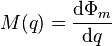
The basic premise behind the Memristor, is that it's resistance changes with current.  So the more current that flows through the element in the positive direction the higher the resistance rises.  When current flows in the opposite direction, the lower the resistance drops.  It's that simple.  How sensitive this device is to current depends on it's Memristance Factor.  Hopefully, when production on this element is begun, more information will be available.  Below is the formula taken from Wikipedia:

Change in Flux versus the change in charge

Applications
The reason this is such a great device for the future is it's extremely small footprint (smaller than any current known transistor configuration).  The vast number of applications include very fast switches and extremely high density non-volatile memory cells.  They have also been brought up to be used to construct a hardware neural network.  These devices, once completely understood, will revolutionize the industry in all aspects, from processor power, memory, to artificial intelligence.  Look up more detailed information on it's origins and discovery at Wikipedia.

Later...

-----------------
Justin Coulston

This has some information on it's application in Adaptive Networks

Friday, April 2, 2010

RF: Microstrip Passive Conversion

Introduction
There are times when you can't get the values you need in inductances and capacitors when developing in high frequency situations.  Sometimes, this isn't a big deal but when you get up to 1 GHz and need small values of Inductors with high Q, problems occur.  So one way around this is to turn your needed inductor value into a microstrip equivalent.  You can accurately develop an inductor with whatever value you desire with this method.

Keep in mine, this is best understood by those that have done some form of PCB development.

Method of Conversion
In order to convert a value you must first have one.  So once you have determined your L value you must then find the equivalent impedance Zo.  This is a simple step.  Use the following equations to accomplish this:

Eq 1

 Eq 2

 Eq 3


where L is Inductance in Henrys, f is frequency in Hz, and Theta is Electrical Length in Degrees.  This will give you the appropriate Characteristic Impedance for a particular frequency.  If your circuit has to have a high bandwidth, this may not be the best method.

Now use Equation 2 if your inductor is in between 2 nodes.  If one of the inductor nodes are going to ground it's preferable to use Equation 3.  These numbers won't usually make that big of a difference but it can matter at extremely high frequencies.

Once you have the impedance you then need to convert this impedance[Zo] to a width[W] and length for a standard microstrip. (Note: I prefer to use a wave-guide for most of my circuits for ease of use with ground, but I won't cover the equations here).  You will need the substrates thickness[H] (or distance from the top plane to the ground plane), substrate relative dielectric constant[Er].   Since finding the width uses an iterative algorithm it's best to just use software to find it.  Use this site, Microstrip Calculator.

Normally I just use the Linecalc software that is embedded in Agilent's ADS.  This is probably some of the better simulator software on the market.  I recommend it whenever possible to use.  I have extensive knowledge of the program, so if you have questions feel free to get in touch with me.  Hope this has been helpful.  Below I'll place the iterative equation used to find the impedance of a line.


To find the length[L] based on electrical length (degrees) use the following:


[f] frequency in Hz
[Mu_r] relative permeability (usually 1 for circuits)
[epsilon_r] relative permitivity (Rogers 4003=3.55)
[c] speed of light in free space (2.99792e8)
[Theta] Electrical Length in Degrees
[L] Physical Length in Meters

The most common unit for length is mils especially in High Frequency Applications.  To convert from Meters to Mils:


I hope this has been somewhat useful.  If you have questions, feel free to write a comment or email me.  Later

-------------------
Justin Coulston

Tuesday, March 30, 2010

Signal Processing: Receiving Wireless Signals

Introduction
This is my first of many Signal Processing blogs.  I am writing this specifically in response to danong's interest in signal processing.  If there are any interests in particular, please let me know and I'll be sure to write something about the topic.  If I know nothing, I'll talk to some of the experts I work with and learn about the topic.  Just leave me a comment, or start following my blog.

What is Signal Processing?
Based on Wikipedia "Signal processing is an area of electrical engineering, systems engineering and applied mathematics that deals with operations on or analysis of signals, in either discrete or continuous time to perform useful operations on those signals."  I can more or less agree with this statement.  But the extent in which signal processing encompasses the Electrical Engineer is extraordinary.  In order to perform signal processing there are a large number of skills involved including RF/Microwave technology, digital hardware technology, software integration technology, and systems architecture technology/knowledge (just to name a few).  With a combination of these, can signal processing really be done.

I will admit that the least important of these is RF/Microwave technology (my industry) but only to an extent.  Most hobbyists and electrical engineers only work in low frequencies (up to 10MHz).  There are exceptions of course, but it's fairly easy to work with signal processing at low frequencies.  When you start working with higher frequencies, sometimes in the GHz range, or wireless technology, an understanding of RF becomes vital.

So today, I'm going to expand on the RF side of things (assuming you're working in a relatively high frequency application (>100MHz).

Basic components to receive an RF signal
I have included a simple block diagram of the essential components required to receive an RF signal.  It should be relatively straight forward to understand.


  • Antenna: The antenna is where the data comes in.
  • Protection Circuitry: This circuitry protects the rest of the components, say from lightning or overbearing signal strength.
  • Filter Network: The filter network separates your signal from other stray signals in the air.  It can comprise of 10 different filters that use switches (like in some radio systems) or an adjustable filter for different frequencies, or just a single frequency filter.
  • Limiter: Typically, you will want to use a limiter to protect your amplifier.  Most of the time an amplifier will be limited by input power.  This stage can be ignored if you limit the protection circuitry enough.  But there may be a lot of loss in the filters so it really depends on design.
  • Amplifier: This is the stage where you drive the signal to an appropriate level.  It higher-end systems, use an LNA (low-noise amplifier) to drive this stage.  It's helpful to keep as little noise from incurring in the process.
  • Processing Circuit: This stage really is the bulk of what is going on in a system.  This stage can include a demodulator, FPGA to analyze the signal, etc.  Really, this is where you decipher the RF signal into usable data.
That's about it.  It's simple enough.  If you have these basic stages, you can receive about any signal safely.  Keep in mind that extensive design can go into each stage.  If you have specific questions, be sure to ask me.  Follow me and comment!

--------------------
Justin Coulston
justin.coulston@gmail.com

Saturday, March 27, 2010

Component Selection: Best Inductors on the Market

When it comes to quality, there is only one place to buy inductors: Coilcraft. Coilcraft has a wide selection of inductors and when you get to high frequencies, very good Q Factors.  But you can't just take my word for it, you need to try them for yourself, and Coilcraft makes it easy by allowing you to order samples.  All you have to do is find the coils you like and click request samples.  Then they'll send you the samples within a few days.  They pride themselves on satisfying the customer and quickly.

I use (in particular) the Mini Spring Air Core Inductors.  These have a small footprint and have "ok" tolerances (2%,5%,10% for many values).  Since a lot of High-Frequency designs require minimal inductors, it's very easy to design around these 10 values.  But let's say that you need a little more precision and different values.  You can always use the smaller Micro Spring Air Core Inductors.  They have precision to 2-digits.

So go out and sample some of these inductors.  They are the best Inductor company in customer satisfaction. They have quality parts that are used in the most strenuous military applications.  They guarantee quality and deliver it.

If you are needing Inductor equations, here you are:

Eq 1: Reactance Equation


Eq 2: Frequency to Angular Frequency

Eq 3: Voltage Differential Equation

Eq 4: Quality Factor
[R]: parasitic resistance of Inductor (Ohm)

Eq 5: Stored Energy in inductor L
[L] inductor (H)
[I] current through inductor (A)

Eq 6: Air Core Inductor Measurement
[r] outer radius of inductor (in)
[N] number of turns
[l] length of inductor coil (in)
[L] Inductance (uH)


Monday, March 22, 2010

RF: High Frequency Filter Design Considerations

There are times as an Electrical Engineer when you just wish to be given the answer to all your High Frequency Design issues.  Unfortunately, I'm not here to do that.  Instead, I'm going to give you a basic way to view all High Frequency Application design.  I'll use the design of a filter as an example.

Filter Design Basics
To start, you need a basic understanding of filter design.  There are 4 main filter types (5 if you include All-Pass Filters): Low-pass, High-pass, Bandpass, Band-reject/Bandstop.  These 4 types are the building blocks of all filtering schema.  The two we will focus on primarily are Low-pass and High-pass filters.

Figure 1: Low-pass Lumped Element Example


Figure 2: High-pass Lumped Element Example

An Electronic Filter by definition is an object or process that removes undesired components or features.  In our usage, an Electronic Filter is a hardware arraignment that allows and rejects certain frequency ranges.  There are many ways to create filters.  Filters can be constructed with lumped elements, waveguides, microstrips, and more.  Each of these construction types has certain characteristics that make them better to design with than others.  The main characteristic most engineers are concerned with are bandwidth capabilities and the amount of space the filter will take up.

Since we are talking about "High Frequency" filters we would do best to talk about microstrip design.  Unfortunately, this topic is very extensive and too detailed to put in one post (if you would like more information on this feel free to email me).  So I will stick with the basic lumped element structure that all filters are based.

Lumped Elements (Capacitors, Inductors, Resistors)
Realistically, lumped elements can be used to design filters up to 4 GHz. Most people, though, cannot accomplish this easily.  Even the most skilled engineers can only design filters up to 2 GHz.

So why is this so difficult?

The difficultly lies in the in the fact that no components are perfect.  Inductors, Capacitors, and Resistors all have something called parasitics that naturally occur due to the physical construction of the parts.  Below are the (more) accurate models for a capacitor and inductor.

Figure 3: Capacitor Model


Figure 4: Inductor model

As you can see, each model has elements of the other fundamental components.  If you look at an inductor, you'll notice that the windings are turned very close together.  This close proximity creates a capacitance in parallel with the ideal inductor.  Also, since there are no super-conductors in use in practical electronics, we have a resistance due to the wire (AKA Equivalent Series Resistance).  The same is true for the capacitor.  There is a parasitic resistance and inductance due to the leads of the capacitor.  All this information can be obtained from a parts datasheet.

Some Component Manufacturers:

Manufacturers are constantly trying to eliminate these parasitics because they are "unwanted" characteristics of parts.  These "unwanted" characteristics become vital at frequencies above 900MHz.  These problems occur when the reactances of the parasitics become very close to each other.  As frequency increases, say for instance within an inductor, the inductor's L will rise higher and higher while the capacitance will go lower and lower based on the below equations:


Equation 1: Capacitor Reactance Equation


Equation 2: Inductor Reactance Equation

When these two reactances are equivalent, we call this the resonant frequency.  This frequency is where the the function of the component switches.  After this point a capacitor then acts like an inductor and an inductor acts like a capacitor.  The resonant point of a component is vital in deciding what manufacturer to purchase from.  If you are trying to obtain adequate results, lets say at 2GHz, but your component's resonant frequency is close to 600MHz, this component will not do the you any good (unless of course you'd prefer it to be used as an inductor).

Example High Frequency Filter
Below I have the circuit and gain response of a simple High-pass filter (cutoff at 1.6GHz) excluding the natural parasitics.  You can see, the response is relatively flat and there are no known issues (minus the fact that it doesn't get very close to 0dB).

Figure 5: 5th-Order Chebyshev High-pass Filter


Figure 6: Gain Response of High-pass circuit (no parasitics)

Now look at the new circuit with included parasitics (Note: I used common parasitic values. They are close to parts I regularly use).

Figure 7: 5th-Order Chebyshev High-pass Filter (w/ Parasitics)


Figure 8: Gain of High-pass Filter (w/ Parasitics)

The differences may be subtle but can be drastic the higher in frequency you go.  Since this filter is running at the 1.6GHz level, there aren't a lot of issues.  Still there are a number of parasitics not taken into account.  If you were to take realistic data, you would notice large downward spikes in the passband.  These are due to grounding issues on the board and parasitics within the PCB board itself.  These can become relatively important especially past 2GHz.  A note to add on this blog, is that I used B2Spice to do the calculations.  Unfortunately, I'm not as familiar with this software as I am with ADS (Agilent's Advanced Design System) which in my opinion is a much stronger piece of software.  Unfortunately, I don't have private access to this software and must settle with B2SPICE for the time being.

I hope this tutorial was helpful, in the very least, in teaching you how high frequency components must take into account the effects of parasitics.  You should include parasitics in all simulations (whether filters or not) above 500MHz (and some below depending on components).  They become a driving point in design.

I have below a few books available on Amazon.com that can be useful in filter design.  I have used these personally and know that they can explain this topic in a much better way than I.  If you have questions or topics you wish to here about, respond to this post or email me at: Justin.Coulston@gmail.com.

----------------------------
JColinator
RF Hardware Electrical Engineer
B.S. Electrical Engineering

Notes: This book is a little dry but very informative if you can follow along.  It's a complete proof on Filter and Filter Synthesis


Notes: I use this book at work on a regular basis.  It has all the basics of RF circuit design.  It contains more detailed information on microstrip filter design and lumped element design.  It also goes over all the basic of circuit parameters (ABCD-parameters, S-parameters, etc)


Notes: Another favorite book of mine that goes into the same kind of depth the RF Circuit Design book does.  This one, though, has more information specific to wireless design including Antenna Design and practical techniques.